Twelve More Feet: Extending a CT Lead on Shelly Pro 3EM with Phase Calibration
A Shelly US customer needed longer CT leads on Shelly Pro 3EM. I cut one, soldered in an extra 12 feet of wire, and used Phase Calibration with an untouched CT as the reference to get the meter reading accurately again on 240 V split-phase service.
A customer called our office recently with a question I've heard more than once. They had Shelly Pro 3EM ready to go on their 240 V split-phase service, but the current transformer (CT) leads weren't long enough to reach where they needed them. Could they just make the wires longer?
You can. But the meter won't read the same afterward. Cutting a CT lead and splicing in more wire changes the resistance on that CT, so the channel starts reading differently from its factory calibration. On an energy meter, a channel that's off by a few percent is a channel you can't trust.
So I tried it myself. I took one of the CTs, cut the lead, and soldered in an extra 12 feet of wire. Then I used the Phase Calibration feature in Shelly Pro 3EM to bring that channel back in line. It worked, and the whole calibration takes about five seconds once everything is wired up. Getting it wired up is the part worth explaining.
How Phase Calibration works
Phase Calibration compares the extended CT to a CT that has never been cut, while both of them measure the same current at the same voltage. It then adjusts the extended channel to match the untouched one.
On split-phase service, a typical install only uses channels A and C. That leaves CT B sitting there unused and unmodified, which makes it the reference for this procedure.
Normally, Shelly Pro 3EM is wired like this on split-phase service:
- Line input C: Leg 1 (L1). This input also powers the device.
- Line input A: Leg 2 (L2)
- Line input B: Not connected
- N: Neutral
- CT A (IA): Clamped on the L2 conductor, arrow toward the load
- CT C (IC): Clamped on the L1 conductor, arrow toward the load
Each CT has to be on the same leg as the line input for its channel. This matters a lot here, because the reference channel and the channel you're calibrating have to see the same voltage. L1 and L2 both read about 120 V to neutral, but they're opposite in phase. Put a CT on one leg and its line input on the other and the readings are wrong, calibration or not.
Warning: These steps involve work inside an electrical enclosure or panel. Only a qualified person should do them. Turn off the breakers that feed Shelly Pro 3EM before you change any wiring at its terminals.
What you need
- Shelly Pro 3EM, added to the Shelly Smart Control app and updated to the latest firmware.
- The device profile set to Triphase, which is the default.
- One Shelly CT that has never been cut or extended, the same type as the others. The CT that came with the meter for channel B works, or a spare Current Transformer for Pro 3EM - 120A.
- A short piece of wire to connect Line input B temporarily, 20 to 14 AWG to fit the terminal.
- A load of at least 500 W you can turn on during calibration. A 1500 W space heater is a good choice. Shelly Pro 3EM won't calibrate below 500 W.
The splice
This is where the 12 feet of wire comes in, and where most of the trouble starts if it's done carelessly. Each CT wire has to connect to the same extension wire all the way to the terminal, and the two wires can't be swapped. Every connection has to be tight and insulated. A loose joint is one of the first things to check if calibration fails.
Calibrating channel C (L1)
Use these steps if you extended the lead on CT C. If you extended CT A instead, skip to the next section.
- Check the splice on the extended lead, as described above.
- Turn off the breakers that feed Shelly Pro 3EM.
- Connect Line input B to L1, the same leg as Line input C. One easy way is to land it on the breaker that feeds Line input C, if that breaker accepts a second conductor.
- Connect the reference CT to the CT B input (IB), if it isn't connected already.
- Clamp the reference CT on the same L1 conductor as CT C. Point both arrows the same way, toward the load.
- Turn the breakers back on and wait for Shelly Pro 3EM to connect.
- Turn on the test load. It has to run on L1, draw at least 500 W, and be on a circuit that only consumes power (no solar or other generation).
- Open Shelly Pro 3EM in the Shelly Smart Control app. Phase B and Phase C should both show positive power of 500 W or more, at close to the same value. If either one shows negative power or the values are far apart, check the troubleshooting section before going on.
- Go to Settings, then Phase Calibration.
- Select Phase C as the phase to calibrate and Phase B as the From Phase.
- Tap Calibrate and leave the load running. It takes about 5 seconds.
- Restart Shelly Pro 3EM when it finishes. If the app doesn't offer a restart, turn its breaker off and back on.
- With the load still running, compare Phase B and Phase C. They should now show nearly the same power.
Wiring diagram
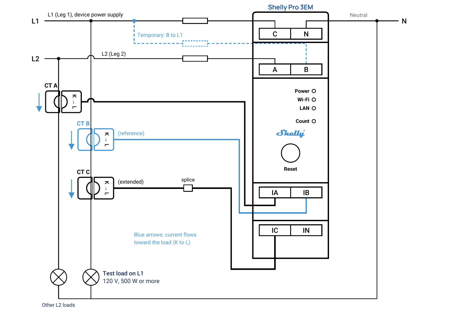
Calibration setup for channel C. Line input B is connected to L1 only for calibration, and the reference CT is clamped on the same L1 conductor as the extended CT C.
Calibrating channel A (L2)
Use these steps if you extended the lead on CT A. If you extended both CT A and CT C, calibrate channel C first, then do this section.
- Check the splice on the extended lead.
- Turn off the breakers that feed Shelly Pro 3EM.
- Connect Line input B to L2, the same leg as Line input A. If B is still on L1 from the previous section, move it.
- Clamp the reference CT on the same L2 conductor as CT A, both arrows toward the load.
- Turn the breakers back on and turn on a test load of at least 500 W that runs on L2. A 240 V load like a water heater or dryer draws current on both legs, so that works too.
- In the app, check that Phase A and Phase B both show positive power of 500 W or more.
- Go to Settings, then Phase Calibration. Select Phase A as the phase to calibrate and Phase B as the From Phase, then tap Calibrate.
- Restart Shelly Pro 3EM, then confirm that Phase A and Phase B show nearly the same power.
Putting it back to normal
Don't leave the reference CT and Line input B connected when you're done. With both in place, Shelly Pro 3EM counts the same current twice and your totals will be wrong.
- Turn off the breakers that feed Shelly Pro 3EM.
- Disconnect the temporary wire from Line input B and from the breaker.
- Remove the reference CT from the conductor. You can leave it plugged into IB or take it out.
- Turn the breakers back on.
- In the app, confirm that Phase A and Phase C show positive power and Phase B shows no load.
The calibration is stored on Shelly Pro 3EM, so it stays in place after the temporary wiring comes out.
Troubleshooting
- Phase B or the extended phase shows negative power. Likely cause: That CT is reversed, with its arrow pointing away from the load, or the measured circuit is generating power. Fix: Flip the CT so its arrow points toward the load, and use a test load on a circuit that only consumes power.
- Phase B and the extended phase read far apart before calibration. Likely cause: Line input B is on the other leg, or the CTs are on different conductors. Fix: Move Line input B to the same leg as the channel you're calibrating, and clamp both CTs on the same conductor.
- Calibration fails. Likely cause: The load is below 500 W. Fix: Use a larger load, or add a second load on the same leg.
- Calibration fails with enough load. Likely cause: The two channels don't see the same voltage or the same current. Fix: Confirm Line input B is on the correct leg and both CTs are on the same conductor with arrows in the same direction.
- Calibration fails again. Likely cause: The splice is loose, or the CT is the wrong type (it has to be the Shelly CT made for this meter). Fix: Redo the splice, check the CT type, and try again.
- Readings still differ after calibration. Likely cause: The device wasn't restarted, or the CTs measured different conductors. Fix: Restart Shelly Pro 3EM and repeat the check with both CTs on one conductor.
- You want to undo a calibration. Fix: In Settings, use Phase Calibration Reset to return the phase to factory calibration, then restart.
A CT lead that comes up short doesn't have to change where you put the meter. Splice it carefully, calibrate it against a CT nobody has touched, and the numbers line up again.
Shelly Pro 3EM specifications
From the Shelly Knowledge Base, with measurements converted to imperial units.
Physical
- Size (H x W x D): 3.70 x 0.75 x 2.72 in (±0.02 in)
- Weight: 2.19 oz (±0.04 oz)
- Mounting: DIN rail
- Shell material: Plastic, white
- Screw terminal max torque: 3.5 lb-in
- Conductor size: 20 to 14 AWG, solid, stranded or bootlace ferrules
- Conductor stripped length: 0.24 to 0.28 in
Environmental
- Ambient temperature: -4 °F to 104 °F
- Humidity: 30% to 70% RH
- Max altitude: 6,562 ft
Electrical
- Power supply: 100 to 260 V AC, 50/60 Hz
- Power consumption: Less than 3 W
- External protection: Circuit breaker, B or C tripping characteristic, 16 A max rated current, 6 kA minimum interrupting rating, energy limiting class 3
Metering
- Voltage measurement: 100 to 260 V RMS per phase, ±1%
- Current measurement: 0 to 120 A RMS per phase and neutral, through CTs
- Current accuracy: ±1% from 2 to 120 A, ±2% from 1 to 2 A, ±5% from 0 to 1 A
- Compatible CT: CT 120A
- Measured values: Active and apparent power and energy, power factor, fundamental active and fundamental reactive energy
- Active energy accuracy: Class B, 1%
- Minimum load for channel-to-channel calibration: 500 W per channel
- No-load threshold: 30 VA per channel
- Data storage: At least 45 days at 1-minute resolution
- Data export: CSV for recorded power quality values, JSON over RPC
- Internal temperature sensor: Yes
Connectivity
- Ethernet: 1 x RJ45
- Wi-Fi: 802.11 b/g/n, range up to about 100 ft indoors and 165 ft outdoors, depending on conditions
- Bluetooth: 4.2, range up to about 33 ft indoors and 100 ft outdoors, depending on conditions
- RF band: 2400 to 2495 MHz, max RF power under 20 dBm
- Local and remote access: HTTP, WebSocket and MQTT, with TLS on all inbound connections
- Webhooks: 20, with 5 URLs per hook
- Scripting: Yes
- CPU and flash: ESP32-D0WDQ6, 16 MB flash
Ethernet, Wi-Fi and Bluetooth can each be turned on or off on their own. Normal timekeeping comes from internet time sync. If the network connection drops, a built-in real-time clock keeps the timestamps going.
Inputs and controls
- Line inputs: 4 screw terminals (3 L, 1 N)
- CT inputs: 4 (3 for L, 1 for N - only 3 CTs are included: A, B, C)
- Button: Short press toggles the add-on relay, hold 5 seconds for the device access point, hold 10 seconds for factory reset
- LEDs: Power, Wi-Fi, LAN and Count
Good to know
- Shelly Pro 3EM has no built-in relay. Controlling a contactor needs a Shelly Pro 3EM Switch Add-on to control a contactor.
- Plug in or unplug the LAN cable only when the device is powered off.
- High voltage is present on the add-on interface whenever the device is powered.
- Below 30 VA per channel, power is still shown but no energy is counted, and a "No load threshold" notice appears.
- The neutral CT is optional and isn't included - on split single phase you can use one CT on L1, a second on L2 and the left over CT ion neutral - you must always use the CT and terminal labelled C on L1 or L2 - this powers the meter.
- Phase sequence error detection is optional and works from the phase voltage zero crossings.
Resources